

Report: Testing of a Beam in Pure Bending
1. Objective of Testing a Beam in Pure Bending
- i. To observe the cracking load, yielding load, ultimate load, as well as crack propagation and crushing of concrete at the ultimate state when analyzing a Beam in Pure Bending.
- ii. To understand the ductile response of reinforced concrete under monotonic loading.
2. Theory: Understanding a Beam in Pure Bending
When studying a Beam in Pure Bending, subjected to monotonically increasing loading to resist an imposed bending moment, it goes through three distinct stages before complete failure. This principle is fundamental in structural engineering.
- Un-cracked stage: Concrete resists tension up to its cracking moment.
- Cracked stage: Tension is transferred completely to the steel reinforcement.
- Ultimate strength stage: Extreme compression fibers of concrete reach their ultimate strain, and the reinforcement yields.
Behavior Under Load
Bending causes tension in the portion lying below the neutral axis and compression above the neutral axis. Therefore, the beam is reinforced on the tension side with steel so that the tension force is taken up by the reinforcement.
Concrete and steel act simultaneously with increasing load. The tension steel undergoes large plastic deformation while the tension force remains constant. This results in increased strain in the extreme compression fiber, shifting the neutral axis upwards. The flexural strength of the section is reached when the extreme compression fiber of the concrete attains its ultimate strain.
Limit State Method Design
The depth of the Neutral Axis (xu) is determined by equating internal compression (C) and tension (T) forces:
Moment of Resistance (MoR) Equations:
-
i. Under-Reinforced Section (xu < xu,max):
\[ MoR = 0.87f_{y}A_{st}(d – 0.42x_{u}) \]
-
ii. Over-Reinforced Section (xu > xu,max):
\[ MoR_{limiting} = 0.36f_{ck}bx_{u,max}(d – 0.42x_{u,max}) \]
3. Materials and Apparatus for Beam in Pure Bending Test
3.1 Materials
- i. Cement
- ii. Sand
- iii. Aggregates
- iv. Water
- v. Steel bars (2 numbers of 8 mm Fe500)
3.2 Apparatus
- i. Beam and Cube Moulds
- ii. Universal Testing Machine (UTM) and Compressive Testing Machine (CTM)
- iii. Vibrator
- iv. Shovels and Mixing Trays
- v. Weighing Machine
- vi. Hack-saw and Rebar Bending Tool
- vii. Measuring Tape
4. Procedure for Testing a Beam in Pure Bending
The following steps outline the meticulous process required to prepare and test a Beam in Pure Bending.
- The formwork was cleaned, prepared, and properly greased with oil.
- Two 8 mm steel bars were cut to a straight length of 700 mm, and the edges were bent to 100 mm for side anchorage (total bar length 900 mm).
- The concrete mix was prepared from the calculated amounts of cement, sand, aggregate, and water in the specified proportions.
- The bottom of the formwork was filled with the concrete mix up to a 25 mm cover depth.
- The steel bars were placed on top of the cover, and the remaining concrete mix was poured, vibrated, and allowed to settle for 24 hours.
- Six concrete cubes (150 mm × 150 mm × 150 mm) were cast simultaneously with the beam.
- After 24 hours, the formwork was removed. The beam and cubes were cured in water for 28 days before testing was conducted in the laboratory.
5. Observation and Calculation for Beam in Pure Bending
Accurate observations are crucial when evaluating the performance of a Beam in Pure Bending. The following data details the mix design and theoretical calculations.
5.1 Mix Design & Weight Calculations
Given Parameters:
- Mix Proportion: 1: 1.5: 3 (Grade M20)
- Sum of Ratio: 1 + 1.5 + 3 = 5.5
- Theoretical W/C Ratio: 0.45
Material Densities:
- Cement: 1440 kg/m3
- Sand: 1600 kg/m3
- Aggregate: 1700 kg/m3
Volume Computations:
- i. Volume of 2 Beams:
2 × 0.75 m × 0.15 m × 0.15 m = 0.03375 m3 - ii. Volume of 6 Cubes:
6 × 0.15 m × 0.15 m × 0.15 m = 0.02025 m3 - iii. Total Wet Volume:
0.03375 + 0.02025 = 0.054 m3 - iv. Total Dry Volume (+55%):
0.054 m3 × 1.55 = 0.0837 m3
Theoretical Material Weights (w/c = 0.45):
- i. Cement: (1/5.5 × 0.0837) × 1440 = 21.91 kg
- ii. Sand: (1.5/5.5 × 0.0837) × 1600 = 36.52 kg
- iii. Aggregate: (3/5.5 × 0.0837) × 1700 = 77.61 kg
- iv. Water: 0.45 × 21.91 kg = 9.86 kg
Actual Batch Weights Taken:
- i. Cement: 26.0 kg
- ii. Sand: 39.0 kg
- iii. Aggregate: 78.0 kg
- iv. Water: 11.7 kg
5.2 Beam Data & Theoretical Calculations
Section Properties:
- Provided length (l): 750 mm
- Effective span (L): 600 mm = 0.60 m
- Breadth (b): 150 mm
- Overall depth (D): 150 mm
- Clear cover: 25 mm
- Effective depth (d): 150 – 25 – (8/2) = 121 mm
Material Properties:
- Area of steel (Ast): 2 × (π/4) × 82 = 100.53 mm2
- Grade of concrete (fck): 20 MPa
- Grade of steel (fy): 500 MPa
Neutral Axis & Moment of Resistance
5.3 Experimental Observations
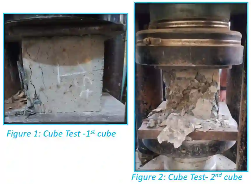
Concrete Cubes Test Data (150 mm × 150 mm)
| Test Period | Cube No. | Weight (kg) | Failure Load (kN) | Compressive Strength (MPa) |
|---|---|---|---|---|
| 7 Days | 1 | 8.415 | 430.0 | 19.11 |
| 2 | 8.590 | 385.0 | 17.11 | |
| 3 | 8.520 | 377.0 | 16.75 | |
| Mean | – | 397.3 | 17.65 | |
| 28 Days | 1 | 8.375 | 650.0 | 28.89 |
| 2 | 8.580 | 750.0 | 33.33 | |
| 3 | 8.145 | 810.0 | 36.00 | |
| Mean | – | 736.7 | 32.54 |
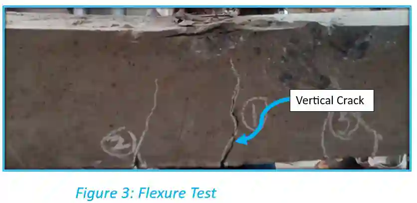
Beam Flexure Test Data
| Beam No. | Crack Width | First Crack Load (kN) | Failure Load P (kN) |
|---|---|---|---|
| 1 | 6 mm | 35.9 | 83.3 |
| 2 | 6 mm | 29.7 | 85.0 |
| Mean | 6 mm | 32.8 | 84.15 |
Experimental Moment Calculation
For two-point loading configuration M = (P · L) / 6:
6. Results of the Beam in Pure Bending Test
The final outcomes summarize the structural capabilities observed during the testing of the Beam in Pure Bending.
7 Days Compressive Strength
17.65 MPa
28 Days Compressive Strength
32.54 MPa
Initial Crack Load
32.8 kN
Moment at Mid Span
8.42 kNm
Avg. Ultimate Load of Beam
84.15 kN
7. Discussion and Conclusion on Beam in Pure Bending
The flexure test demonstrated a classic ductile failure for an under-reinforced section, characteristic of a Beam in Pure Bending, marked by progressive flexural cracking, steel yielding, and ultimate concrete crushing. The experimental moment capacity (8.42 kNm) exceeded the theoretical design (4.55 kNm). This was primarily due to the actual 28-day concrete strength (32.54 MPa) testing significantly higher than the nominal M20 grade. Ultimately, the experiment successfully verified the theoretical equations and the safe, ductile warning behavior of under-reinforced concrete when subjected to pure bending.