

Report: Testing of a Beam in Pure Shear
1. Objective of Testing a Beam in Pure Shear
- i. To know about the modes of shear failure in a reinforced concrete (RC) beam.
2. Theory: Understanding a Beam in Pure Shear
Shear force is present in a beam where there is a change in bending moment along the span. It is equal to the rate of change of bending moment. Several experimental analyses of shear in concrete beams are quite complex, but they have been conducted to understand the various modes of failure which could occur due to a possible combination of shear and bending moment acting at a given section.
Modes of Failure
The primary modes of shear failure in concrete are:
- Diagonal tension failure
- Diagonal shear failure
- Diagonal compression failure
Studies have shown that the shear force is resisted by the uncracked concrete in the compression region, the aggregate interlocking, and the shear acting across the longitudinal steel bars. Shear reinforcement, if present, will also significantly resist shear failure.
3. Materials and Equipment
Materials Required
- i. RC Beam of span 700 mm
- ii. M20 concrete
- iii. Fe500 with shear reinforcement
Equipment
- Beam Testing Machine (UTM/CTM setup)
4. Procedures
- The formwork was cleaned, prepared, and greased.
- Longitudinal bars and 2-8 mm φ bars were cut to a length of 800 mm and edges were bent up to 850 mm in each.
- 2-8 mm φ bars were placed at the lower side and 2-8 mm φ bars were placed at the top.
- 3-6 mm φ bars were used for vertical stirrups.
- The concrete mix was prepared from the calculated amount of cement, sand, aggregates, and water in a given proportion.
- The steel framework was placed inside the formwork and was filled by concrete mix by pouring and compacting, and then allowed to settle for 24 hours.
- Three cubes of size 150 mm × 150 mm × 150 mm were also cast simultaneously.
- After 24 hours, the formwork was removed, and the specimens were cured for 28 days before testing was performed on them.
5. Experimental Observations and Calculations
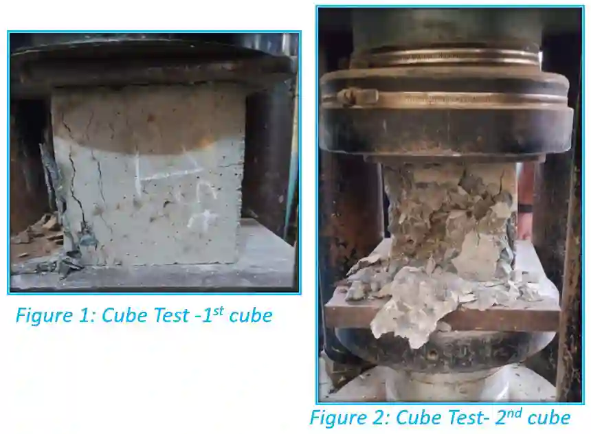
5.1 Concrete Cubes Test Data (28 Days)
| Test Period | Cube No. | Weight (kg) | Failure Load (kN) | Compressive Strength (MPa) |
|---|---|---|---|---|
| 28 Days | 1 | 8.235 | 643.2 | 28.58 |
| 2 | 8.415 | 444.8 | 19.76 | |
| 3 | 8.200 | 666.2 | 29.60 | |
| Mean | – | 584.73 | 25.98 |
5.2 Beam Pure Shear Test Data
| Beam No. | Crack Width | First Crack Load (kN) | Failure Load (kN) |
|---|---|---|---|
| 1 | 4 mm | 35.6 | 105.4 |
5.3 Calculations
Section Properties:
- Dimension of Beam: 700 mm × 150 mm × 150 mm
- Effective depth (d): 150 – 25 – 4 – 6 = 115 mm
- Dead load (w): 0.15 × 0.15 × 0.5 × 25 = 0.5625 kN/m
- Spacing of stirrups (sv): 300 mm
Material Properties:
- Area of tensile steel (Ast): (2 × π × 82) / 4 = 100.53 mm2
- Area of vertical steel (Asv): (2 × π × 62) / 4 = 56.55 mm2
- Grade of steel: Fe500 (tensile), Fe250 (stirrups)
- Grade of concrete: M20
Percentage of Tensile Steel (pt):
Design Shear Strength (τc) from Table 19 of IS 456:2000:
| pt (%) | τc (N/mm2) |
|---|---|
| 0.50 | 0.48 |
| 0.58 | τc (Interpolated) = 0.505 |
| 0.75 | 0.51 |
Note: Maximum shear strength, τc,max = 2.8 N/mm2.
Shear Capacity Computations:
1. Permissible Shear Force by Concrete (Vc):
2. Increment in Shear Resistance Due to Stirrups (Vus):
3. Total Theoretical Shear Capacity (Vu):
4. Practically Observed Shear Resistance (Vexp):
6. Results Summary
The final outcomes summarize the structural capabilities observed during the testing of the Beam in Pure Shear.
28 Days Compressive Strength
25.98 MPa
Initial Crack Load
35.6 kN
Theoretical Shear Capacity (Vu)
13.436 kN
Experimental Shear Resistance
52.7 kN
7. Discussion and Conclusion
The experimental shear resistance of 52.7 kN was significantly higher than the theoretical shear capacity of 13.436 kN as calculated using the code IS 456:2000.
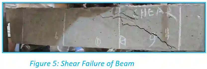
Initially, fine vertical cracks appeared near the mid-span of the beam. As the applied load increased, inclined diagonal cracks developed near the support region and propagated towards the loading point. The beam ultimately failed by diagonal tension shear failure. A crack width of 4 mm was successfully observed prior to the ultimate failure point.