
Software Process Model (SPM)
SDLC, Feasibility Study, System Design & Testing
Complete NEB Class 12 Computer Science notes on Software Process Model — SDLC phases, feasibility study, testing, system design tools (DFD, ER diagram, flowchart), and SDLC models (Waterfall, Prototype, Spiral, Agile) — with fully solved questions.
Core Theory Notes
A project is defined as a sequence of tasks that must be completed to attain a certain outcome. The characteristics of a project are as follows:
SDLC is a process followed for a software project within a software organization. It consists of a detailed plan describing how to develop, maintain, replace, and alter or enhance specific software.
The importance of SDLC is as follows:
SDLC is a process followed for a software project within a software organization. It consists of a detailed plan describing how to develop, maintain, replace, and alter or enhance specific software.
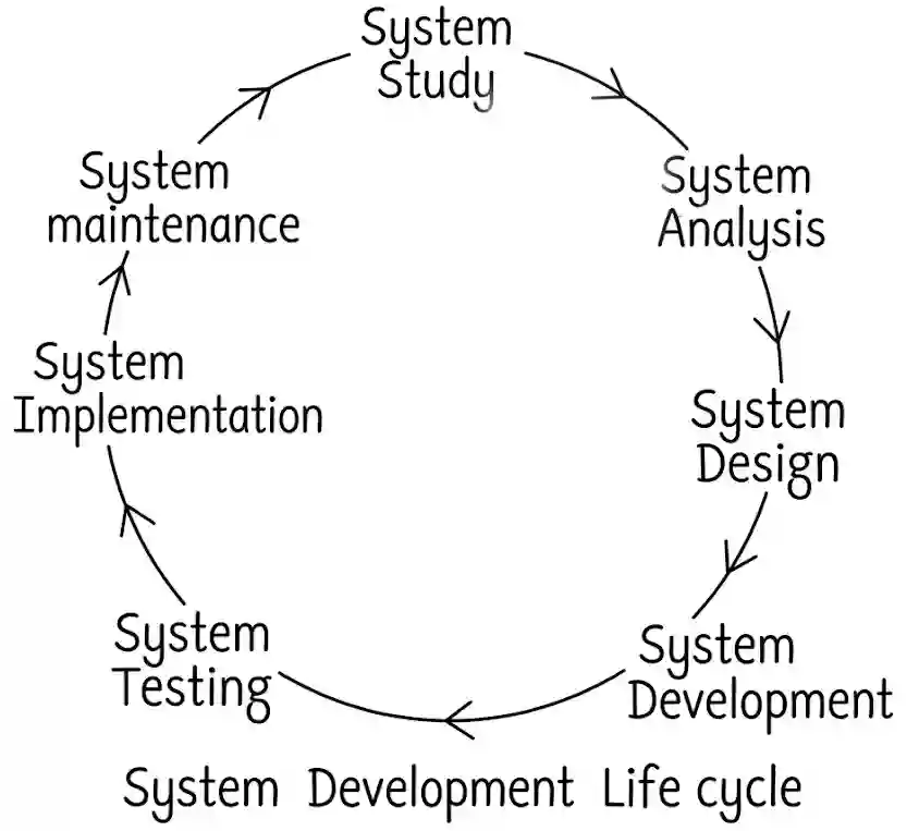
Fig: SDLC Stages
1. System Study
This is the initial and one of the most important phases of SDLC. The purpose of this step is to find out the scope of the problem and determine solutions. Resources, cost, time, benefits, and other items should be considered at this stage. This phase might involve trying to meet or exceed expectations for their employees, customers, and stakeholders too.
2. System Analysis
The second phase is where teams consider the functional requirements of the project or solution. System analysis is a process of collecting factual data, understanding the processes involved, identifying problems, and recommending feasible suggestions.
3. System Design
System design is the most creative and challenging phase of the system life cycle. The design phase is the “architectural phase” of the system life cycle. This phase describes, in detail, the necessary specifications, features, and operations that will satisfy the functional requirements of the proposed system.
4. System Development
Now the real work begins; the development phase marks the end of the initial section of the process. After the design stage is complete, the final program specification and the file design are handed over to the programmer. Then, the programmer begins to develop the program by using a suitable High-Level Language (HLL).
5. System Testing
Once the program modules are ready, each of the program modules is tested independently as per the specifications of the users and debugged. This step is the most complex, most time-consuming, and most expensive step in SDLC.
6. System Implementation
After the new system is ready, it is implemented in the organization. Then the new system becomes a part of the daily activities of an organization. During this stage, applications are installed and loaded on existing or new hardware, and users are introduced to the new system and trained.
7. System Maintenance
When the system is operating in an organization, users sometimes find problems with how it works and often think of better ways to perform its functions. When the time changes, the requirements of the organization also get changed, and the existing system cannot fulfill them.
A feasibility study aims to provide an independent assessment that examines all aspects of a proposed project, including technical, economic, financial, legal, and environmental considerations.
1. Technical Feasibility
It is concerned with specifying different devices and software for the new system. It determines the required devices which are necessary for the development of the new system and whether they are available or not.
2. Operational Feasibility
It is mainly related to human skills and political aspects. It assesses if the current staff can work in the new system after training or not. If the whole staff needs a very long time and more cost to be trained in the new system, then the new system will not be feasible.
3. Legal Feasibility
It is mainly focused on analyzing any violation of government laws or not. Legal feasibility of the project determines whether the proposed system conflicts with legal requirements like any data protection act or any social media law.
4. Schedule Feasibility / Time Feasibility
It is concerned with whether the time required for the development of the new system is feasible or not. If a deadline (time limit) is established, it is called schedule feasibility.
5. Behavioral Feasibility
It evaluates and estimates the user attitude or behavior towards the development of the new system. It helps in determining if the system requires special effort to educate, retrain, transfer, and make changes in an employee’s job.
System Analyst
Software Engineer
Introduction: A system analyst is a person who guides the analysis, design, implementation, and maintenance of a given system. A system analyst is involved in the SDLC, studying the problems of the system, interacting with customers, preparing documentation, planning solutions, and also helping programmers with coding.
Roles:
Characteristics / Attributes and Qualities of a System Analyst
Communication Skills: System analysts spend a great deal of time engaging with users, consumers, management, and developers according to the nature of the work. The performance of a project may rely on the system analyst clearly communicating information such as project specifications, adjustments required, and results of testing.
Technical Skills: An analyst should know what IT technologies are being used in order to find system solutions, what new potential results can be accomplished across existing systems, and what the latest technology offers.
Analytical Skills: The skill set of an analyst should include excellent analytical abilities in order to better analyze the needs of a client and convert them into application and organizational requirements. This includes analyzing information, records, user feedback, surveys, and workflows to decide which course of action to take.
Problem-Solving Skills: Although analysts are not always exceptional in the ability to develop workable solutions to problems, it is a required skill to effectively perform the job. As with most IT positions, the career of the system analyst can be spent coping with regular and random modifications.
Decision-Making Skills: The capacity to make decisions is another significant system analyst skill. In a broad range of system problems, the system analyst is called upon for sound judgment as a management figure.
Managerial Skills: The ability to manage projects is another ability a system analyst should possess. This involves planning the scope of the project, directing team members, managing demands for adjustment, predicting budgets, and keeping everyone on the project under assigned time limits.
Software Engineering: Software engineering is an engineering discipline that is concerned with all aspects of software production from the early stages of system specification through to maintaining the system after it has gone into use.
Why Software Engineering is required:
Characteristics of a Good Software Engineer:
Collecting requirements for a project is a very vital part. The collect requirements process helps to define the project scope during scope management. The techniques used to collect requirements are:
System design is the process of defining the components, modules, interfaces, and data for a system to satisfy specified requirements.
Elements of system design:
The Various Subsets of System Design
1) Logical Design: Logical design describes the general functional capabilities of a new system. Data flow and E-R diagrams are used, respectively.
2) Physical Design: The process of actual input and output of the system is related to physical design. The main criteria of physical design are to manage how the data is verified, processed, and displayed as a result.
System Design Approaches
i) Top down
ii) Bottom up
System design tools play an important role in system development.
1) Flowchart
A flowchart is a very important tool for developing an algorithm and program. It is a pictorial representation of the step-by-step solution of a program. Programmers often use it as a program planning tool for visually organizing the steps necessary to solve a problem. It uses boxes of different shapes that denote different types of instructions. It is of the following types:
Program Flowchart
A programming flowchart is a visualization tool programmers use when creating new applications to understand a process, workflow, or algorithm. It typically uses geometric shapes to represent steps and arrows to communicate the flow of data. These programming flowcharts also analyze the logic behind the program to process the code of the programming.
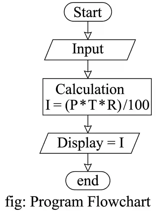
Fig: Program Flowchart
System Flowchart
System flowcharts are graphic illustrations of the physical flow of information through the entire accounting system. Flow lines represent the sequences of the process, and other symbols represent the inputs and outputs to a process.
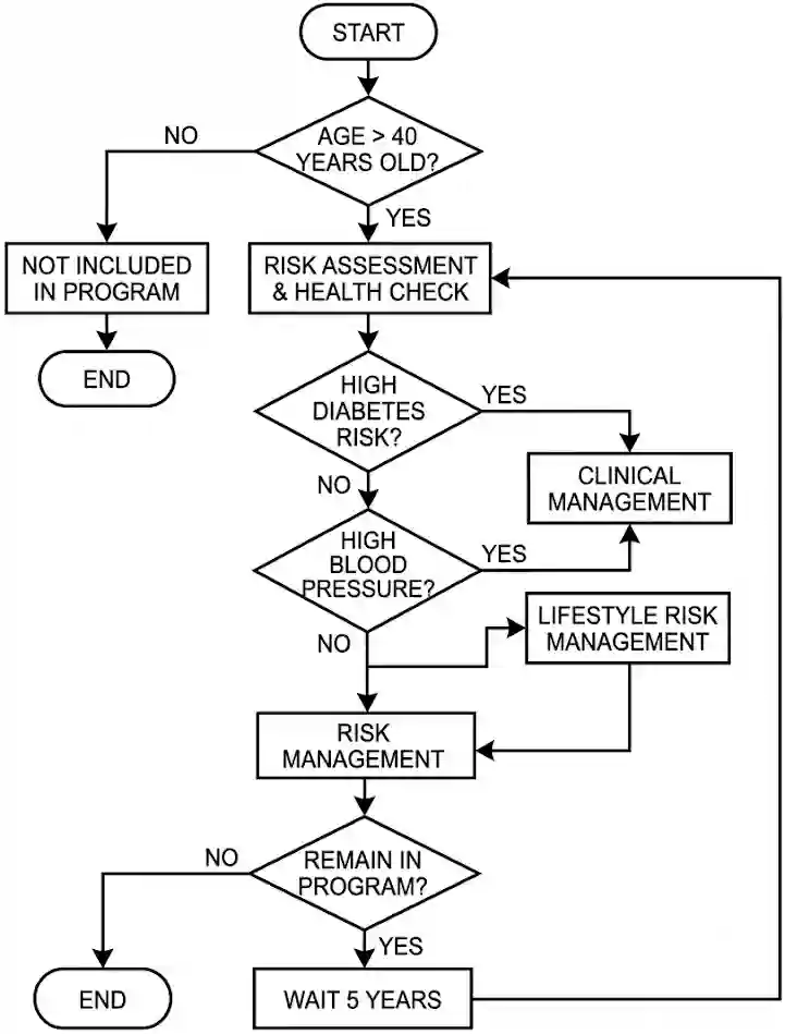
Fig: System Flowchart
A system flowchart shows:
2) Context Diagram
A diagram used to give an overview of an entire system. In a context diagram, there is only one circle/process that represents the entire system. Through this display, a system analyst can model what expected data is going to go into the system, and then after it has been processed by the system, what information will be returning to the external entities.
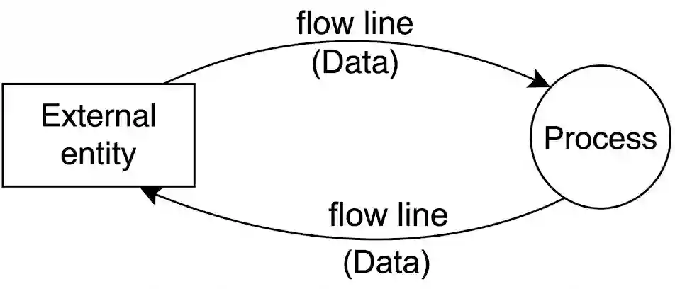
Fig: Context Diagram
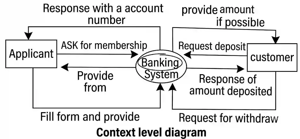
Fig: Context Level Diagram Example
3) Data Flow Diagram
A data flow diagram presents the logical flow of information through a system in graphical or pictorial form. Data flow diagrams have only four symbols, which makes them useful for communication between analysts and users. A data flow diagram (or DFD) is a graphical representation of the flow of data through an information system. It is of three types:
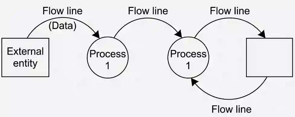
Fig: Data Flow Diagram
4) Entity Relation Diagram
An entity-relationship model (ER model) describes the structure of a database with the help of a diagram, which is known as an Entity Relationship Diagram (ER Diagram). An ER model is a design or blueprint of a database that can later be implemented as a database. An entity is a thing or object in the real world that is distinguishable from its surrounding environment. For example, each employee of an organization is a separate entity. Entities can have relationships with each other.
Facts about ER Diagram model:
Components of an ER Diagram:
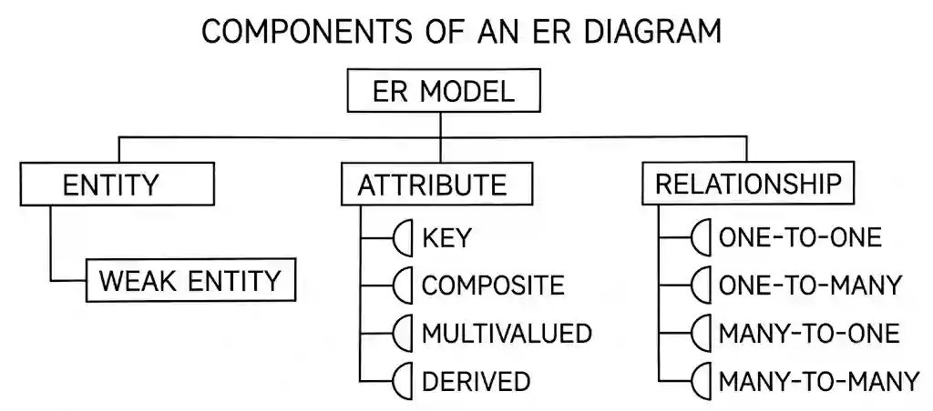
Fig: Components of an ER Diagram
a) Entity: An entity is an object or component of data. An entity is represented as a rectangle in an ER diagram. For example, we have two entities, Student and College, and these two entities have a many-to-one relationship as many students study in a single college.
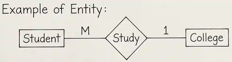
Fig: Entity
b) Attribute: An attribute describes the property of an entity. An attribute is represented as an oval in an ER Diagram.
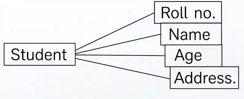
Fig: Attribute
c) Relationship: A relationship is represented by a diamond shape in an ER diagram; it shows the relationship among entities. There are four types of cardinal relationships:
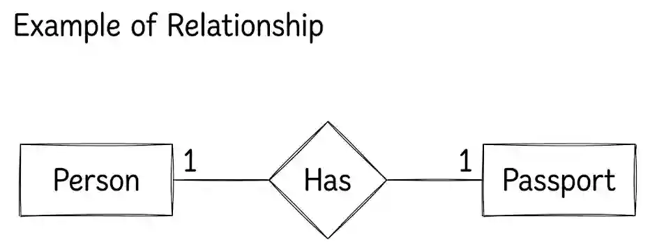
Fig: Relationship
5) Algorithm
An algorithm is a procedure or formula for solving a problem. A computer program can be viewed as an elaborate algorithm. In mathematics and computer science, an algorithm usually means a small procedure that solves a recurrent problem. Algorithm refers to the logic. It is a step-by-step description of how to arrive at the solution to the problem. A good algorithm helps us to create a good program.
An algorithm must possess the following characteristics:
6) Pseudocode
Most programs are developed using programming languages. These languages have specific syntax that must be used so that the program will run properly. Pseudocode is not a programming language; it is a simple way of describing a set of instructions that does not have to use specific syntax. “Pseudo” is “fake” or “false”. So, pseudo-code is ‘fake code’ or ‘false code’. Pseudocode is an artificial and informal language that helps programmers to develop algorithms.
7) Use Case Diagram
A use case is a series of related interactions between a user (or more generally, an “actor”) and a system that enables the user to achieve a goal. A use case describes the system’s behavior as it responds to a series of related requests from an actor. Use cases are the best way to capture functional requirements of a system.
A use case diagram consists of:
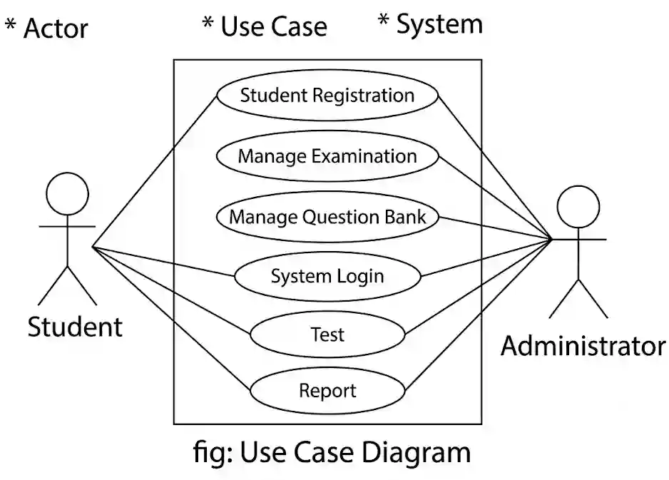
Fig: Use Case Diagram Example
8) Decision Tree Diagram
A decision tree is a set of rules for what to do in certain conditions, and if a particular condition satisfies, do that; otherwise, go to this step. They can be used to enforce strict compliance with local procedures, and avoid improper behaviors, especially in complex procedures or life-and-death situations.
9) Decision Table
A decision table is a table with various conditions and their corresponding actions. A decision table is a two-dimensional matrix. It is divided into four parts: condition stub, action stub, condition entry, and action entry. Condition stub shows the various possible conditions.
Quality: The degree to which a component, system or process meets specified requirements and/or user/customer needs and expectations. Software quality is defined as a field of study and practice that describes the desirable attributes of a software product. The definition is applicable for software as well as for a generic software product.
Key aspects that conclude software quality include:
Different types of SDLC models are:
1) Waterfall Model
The waterfall model is a sequential (non-iterative) design process used for software development. This model is suitable for routine types of jobs in which all the problems are already known. The method is very simple to understand and use and there is no overlapping in the phases. This model describes following of phases downwards one by one.
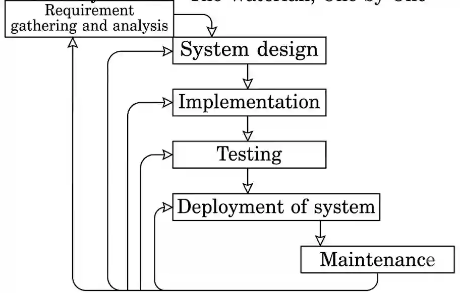
Fig: Waterfall Model
Advantages:
Disadvantages:
2) Prototype Model
A prototype model is a working model that does not normally have all the required features or provide all the functionality of the final system. In this model, it is assumed that all the requirements may not be known at the start of the development of the system.
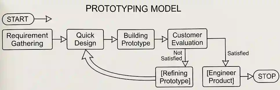
Fig: Prototype Model
Advantages:
Disadvantages:
3) Spiral Model
The spiral model is a software development model designed to control risk. The spiral model repeats steps of a project, starting with modest goals and expanding outward in ever-wider spirals (called rounds). This lowers the overall risk of the project: large risks should be identified and mitigated.
Steps of spiral model:
Advantages:
Disadvantages:
4) Agile Software Development
The Agile software development methodology is one of the simplest and most effective processes to turn a vision for a business need into software solutions. Agile is a term used to describe software development approaches that employ continual planning. It encourages flexible responses to change.
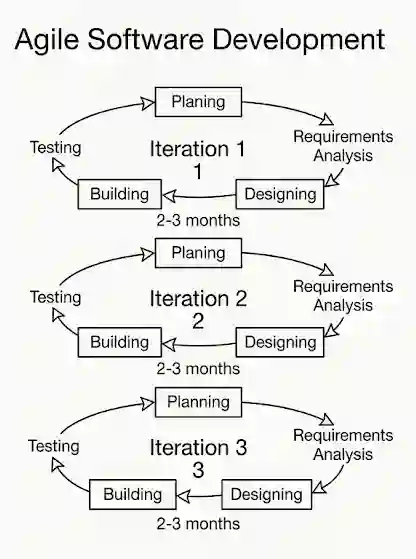
Fig: Agile Software Development
Values:
Principles:
Documentation in software engineering is the umbrella term that encompasses all written documents and materials dealing with a software product’s development and use. All software development products, whether created by a small team or a large corporation, require some related documentation.
Types of User Documentation:
Developer Documentation:
SDLC Exercise Solution: Old is Gold
Short Answer Questions
The different requirement collection methods for the development of software are:
Fig: Agile Software Development
The Agile Software development methodology is one of the simplest and most effective processes to turn a vision for a business need into software solutions. Agile is a term used to describe software development approaches that employ continual planning, learning, improvement, team collaboration, evolutionary development, and early delivery. It encourages flexible responses to change. It aims to help uncover better ways of developing software by providing a clear and measurable structure that promotes iterative development, team collaboration, and change recognition.
Values of Agile:
The importance of system testing of SDLC:
After the development team proposes the new system, the feasibility study or survey is performed in order to determine whether the system will be feasible or not. There are different types of feasibility studies. They are:
The person who guides the analysis, design, implementation, and maintenance of a given system is called a system analyst. The desirable characteristics of a system analyst are:
The roles of a system analyst in SDLC phases are:
The importance of SDLC is as follows:
A sequential design process used for software development is called the waterfall model.
Pros:
Cons:
The different test techniques during system development are:
Documentation in software engineering is the umbrella term that encompasses all written documents and materials associated with a software product in its development and use. The importance of documentation in program design is:
Flowcharts use various symbols to represent different types of actions or steps in a process. These are some common flowchart symbols:
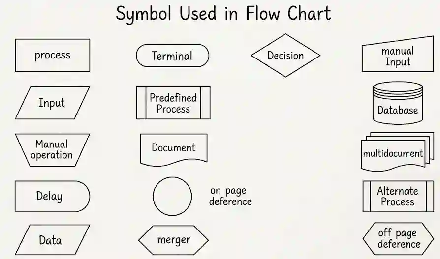
Fig: Symbols used in a Flowchart
| Decision Table | Decision Tree |
|---|---|
| A decision table is a table that indicates conditions and actions in a simplified and orderly manner. | A decision tree is a graphical representation of possible solutions to a decision based on certain terms and conditions. |
| Extended entry table and limited entry table are its types. | Variable decision and continuous variable decision trees are its types. |
| The purpose of a decision table is to structure logic by generating rules derived from data entered in the table itself. | The purpose of a decision tree is to give an effective and easy way to visualize and understand the potential options or decisions. |
The different symbols used to construct a flowchart are the rectangle, diamond, parallelogram, and oval. They are graphic illustrations of the physical flow of information through the entire accounting system. Flow lines represent the sequence of processes, and other symbols represent the inputs and outputs to a process.
Fig: Flowchart Example
An entity-relationship model that describes the structure of a database with the help of a diagram is called an ER diagram. The meanings of graphical symbols used in an ER diagram are:
Fig: Entity
Fig: Attribute
Fig: Relationship
The different program logic tools are:
Program logic is the implementation of the program’s requirements and design. If the design of the application is bad, the program logic can nevertheless be professionally implemented.
The different types of program logic tools are as follows:
SDLC is a process followed for a software project within a software organization. It consists of a detailed plan describing how to develop, maintain, replace, and alter or enhance specific software.
Fig: SDLC Stages
A computer program (software) that uses artificial intelligence (AI) to reproduce the judgment of a human with expert knowledge in a particular field is known as an expert system.
The fields of expert systems are as follows. It is the most important applied area of AI. An expert system contains knowledge about its application domain and uses an inferencing procedure to solve problems that would otherwise require human competence or expertise. They are interactive, trustworthy, computer-based decision-making tools that utilize data and heuristics to address challenging decision-making issues. It is regarded as representing the pinnacle of human systems; its job is to resolve the trickiest problems in a specific field.
The importance of DFD in SDLC are:
A flowchart is a very important tool for developing algorithms and programs. It is a pictorial representation of a step-by-step solution to a problem. Programmers often use it as a program planning tool for visually organizing the steps necessary to solve a problem. It uses boxes of different shapes that denote different types of instructions. While making a flowchart, a programmer need not pay attention to the elements of the programming language.
Fig: Symbols used in a Flowchart
A system flowchart is a graphic illustration of the physical flow of information through the entire accounting system. Flow lines represent the sequences of processes, and other symbols represent the inputs and outputs to a process.
A system flowchart shows:
Fig: System Flowchart Example
Documentation techniques include the methods and tools used to record, organize, and maintain information about a process, system, project, or product. These techniques are essential for ensuring that all relevant details are captured, easily accessible, and comprehensible to stakeholders. Here are some common documentation techniques with examples:
A system is a set of interacting or interdependent components that work together to form a complex whole. The basic elements of a system are as follows:
You can test a newly developed system in the following ways:
Collecting requirements is a crucial activity in project management because the requirements of a project define the project scope. There are different methods for gathering requirements for developing software:
A program algorithm is a procedure or formula for solving a problem. It is based on conducting a sequence of specified actions in which these actions describe how to do something, and your computer will do it exactly that way every time.
Structured Programming is a paradigm that aims to make programs easier to comprehend from a reader’s point of view. It does this by linearizing the flow of control through a program. In structured programming, execution follows the writing order of the code.
📄 View / Download Full PDF Notes
If the PDF doesn’t load, click here to open it in Google Drive.
 Physics (भौतिक विज्ञान)
 Chemistry (रसायन विज्ञान)
 Biology (जीव विज्ञान)
 Mathematics (गणित)
 English (अंग्रेजी)
 Nepali (नेपाली)
 Computer Science (कम्प्युटर विज्ञान)
 Account (लेखाशास्त्र)
 Economics (अर्थशास्त्र)
 Business Studies (व्यवसाय अध्ययन)
 Social (सामाजिक)