
Electromagnetic Induction
Class 12 Physics Notes • NEB Syllabus 2083
Faraday's and Lenz's laws, transformer diagram, working principle and types, 10 solved multiple choice questions, step-by-step numericals, handwritten and typed PDF notes and frequently asked questions.
1. Syllabus
Unit: Electricity and Magnetism
Chapter 18: Electromagnetic Induction (8 hours)
18.1 Faraday's laws; induced electric fields
18.2 Lenz's law; motional electromotive force
18.3 A.C. generators; eddy currents
18.4 Self-inductance and mutual inductance
18.5 Energy stored in an inductor
18.6 Transformer
These notes follow the NEB Class 12 Physics syllabus (+2 Physics, Nepal). Read the quick overview first, practise the multiple choice questions, then work through the numericals, and finish with the PDF notes for quick revision.
2. Electromagnetic Induction at a Glance
Electromagnetic induction is the production of an e.m.f. in a circuit when the magnetic flux linked with it changes. The flux \(\Phi=BA\cos\theta\) can change because \(B\), the area \(A\) or the orientation \(\theta\) changes.
Key laws and formulas
| Topic | Statement or formula |
|---|---|
| Faraday's first law | An e.m.f. is induced whenever the flux linked with a closed circuit changes |
| Faraday's second law | \(\varepsilon=-N\dfrac{d\Phi}{dt}\) |
| Lenz's law | The induced current opposes the change in flux that causes it (conservation of energy) |
| Induced electric field | \(\oint\vec E\cdot d\vec l=-\dfrac{d\Phi}{dt}\) |
| Motional e.m.f. | \(\varepsilon=Blv\); rotating rod \(\varepsilon=\tfrac12B\omega l^2\) |
| AC generator | \(e=NAB\omega\sin\omega t\), peak value \(NAB\omega\) |
| Self-inductance | \(\varepsilon=-L\dfrac{dI}{dt}\); long solenoid \(L=\dfrac{\mu_0N^2A}{l}\) |
| Mutual inductance | \(\varepsilon_2=-M\dfrac{dI_1}{dt}\) |
| Energy stored in an inductor | \(U=\tfrac12LI^2\) |
| Ideal transformer | \(\dfrac{V_s}{V_p}=\dfrac{N_s}{N_p}=\dfrac{I_p}{I_s}\) |
Eddy currents
Eddy currents are circulating currents induced in a bulk conductor when the flux through it changes. They waste energy as heat, so transformer cores are built from thin laminated sheets. They are useful in induction furnaces, induction cookers, electromagnetic brakes and the damping of galvanometers.
Transformer diagram, construction and working principle
Figure: Transformer diagram. The AC supply drives the primary coil; the changing flux in the core induces an e.m.f. in the secondary coil that feeds the load.
Construction: a laminated soft-iron core (thin insulated sheets, to reduce eddy currents and hysteresis loss) carrying two insulated copper windings, the primary connected to the AC supply and the secondary connected to the load. Working principle: mutual induction. The alternating current in the primary produces a changing flux in the core; the same flux links the secondary and induces an alternating e.m.f. in it. A transformer works only with AC.
Types of transformer
| Basis | Type | Description |
|---|---|---|
| Voltage change | Step-up | \(N_s>N_p\); raises the voltage and lowers the current |
| Step-down | \(N_s | |
| Core construction | Core type | Coils wound on two separate limbs of the core |
| Shell type | Both coils on the central limb of the core | |
| Use | Power, distribution, isolation, auto-transformer, instrument (current and potential) | Transmission at the power station, supply to homes, electrical isolation, variable voltage, and measurement of high current and voltage |
Applications, losses and efficiency
Applications: a step-up transformer at the power station raises the voltage so that long-distance transmission carries a small current and little \(I^2R\) loss; step-down transformers supply homes and industry; transformers also run chargers, adapters, welding machines and measuring instruments. Losses in a real transformer are copper loss (\(I^2R\) heating of the windings), iron loss (eddy currents and hysteresis in the core), and flux leakage. The efficiency is \(\eta=\dfrac{P_{\text{out}}}{P_{\text{in}}}\times100\%\), which is 100% for an ideal transformer.
3. Multiple Choice Questions
Question 1. A conducting wire of length 10 cm moves with a velocity of 10 m s\(^{-1}\) at right angles to a magnetic field of flux density 0.01 T. The e.m.f. generated in the wire is:
- a) 0 V
- b) 0.01 V
- c) 0.1 V
- d) 1.0 V
Correct Answer: b) 0.01 V
Reason: The motional e.m.f. is \(\varepsilon=Blv\):
Question 2. Lenz's law is a statement of:
- a) The law of conservation of charge
- b) The law of conservation of energy
- c) The law of conservation of mass
- d) The law of conservation of linear momentum
Correct Answer: b) The law of conservation of energy
Reason: The induced current opposes the change in flux, so mechanical work must be done against the opposing force to change the flux. That work is converted into electrical energy, which is conservation of energy.
Question 3. Which of the following circuit elements will oppose the change in circuit current?
- a) Capacitor
- b) Inductor
- c) Resistor
- d) Resistor and capacitor
Correct Answer: b) Inductor
Reason: A change in the current through an inductor induces a self-induced e.m.f. \(e=-L\dfrac{dI}{dt}\) that opposes the change.
Question 4. A coil having \(N\) turns and area \(A\) is rotated in a uniform magnetic field \(B\) with angular velocity \(\omega\). The maximum e.m.f. induced in the coil is:
- a) \(NAB\omega\)
- b) \(\tfrac12NAB\omega\)
- c) \(\dfrac{NA\omega}{B}\)
- d) \(\dfrac{B\omega}{NA}\)
Correct Answer: a) \(NAB\omega\)
Reason: The flux linkage is \(N BA\cos\omega t\), so
Question 5. A rectangular loop of sides 8 cm and 2 cm, having a resistance of 1.6 \(\Omega\), is placed in a magnetic field of 0.3 T directed normal to the loop. The magnetic field is gradually reduced at the rate of 0.02 T s\(^{-1}\). How much power is dissipated by the loop as heat?
- a) \(1.6\times10^{-4}\ \mathrm{W}\)
- b) \(3.2\times10^{-8}\ \mathrm{W}\)
- c) \(6.4\times10^{-10}\ \mathrm{W}\)
- d) \(12.8\times10^{-8}\ \mathrm{W}\)
Correct Answer: c) \(6.4\times10^{-10}\ \mathrm{W}\)
Question 6. A current of 3 A flowing in the primary coil is reduced to zero in 0.001 s. The induced e.m.f. in the secondary coil is 15000 V. The mutual inductance between the two coils is:
- a) 0.5 H
- b) 5 H
- c) 1.5 H
- d) 10 H
Correct Answer: b) 5 H
Question 7. The magnetic flux linked with a coil is given by \(\Phi=5t^2+3t+6\). The induced e.m.f. in the coil in the fourth second is:
- a) 33 V
- b) 43 V
- c) 108 V
- d) 10 V
Correct Answer: b) 43 V
Reason: The magnitude of the induced e.m.f. is the rate of change of flux:
Question 8. A current varying at the rate of 3 A s\(^{-1}\) in a coil generates an e.m.f. of 8 mV in a nearby coil. The mutual inductance of the two coils is:
- a) 2.67 H
- b) \(2.67\times10^{-3}\ \mathrm{mH}\)
- c) 0.267 H
- d) 2.67 mH
Correct Answer: d) 2.67 mH
Question 9. A coil of wire of radius \(r\) has 600 turns and a self-inductance of 108 mH. The self-inductance of a similar coil of 500 turns will be:
- a) 108 mH
- b) 90 mH
- c) 75 mH
- d) 100 mH
Correct Answer: c) 75 mH
Reason: \(L\propto N^2\):
Question 10. What is the coefficient of mutual induction when the magnetic flux changes by \(2\times10^{-2}\ \mathrm{Wb}\) and the change in current is 0.01 A?
- a) 3 H
- b) 0.5 H
- c) 2 H
- d) Zero
Correct Answer: c) 2 H
4. Numerical and Subjective Questions
a) State Faraday's laws of electromagnetic induction.
First law: whenever the magnetic flux linked with a closed circuit changes, an e.m.f. is induced in the circuit. The e.m.f. lasts as long as the change in flux continues.
Second law: the magnitude of the induced e.m.f. is directly proportional to the rate of change of magnetic flux linked with the circuit:
b) A coil has 5000 turns. What is the e.m.f. produced in the coil when the magnetic flux cutting the coil changes by \(8\times10^{-4}\ \mathrm{Wb}\) in 0.1 s?
c) A light aluminium ring is suspended from a long thread. When a strong magnet is moved away from it, the ring follows the magnet. Why? What would happen if the magnet were moved towards the ring?
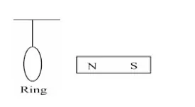
Figure: Aluminium ring and magnet
Magnet moved away: the flux through the ring decreases. By Lenz's law the induced current opposes this decrease, so the ring develops a pole facing the magnet that is opposite to the magnet's pole. The ring is attracted and follows the magnet.
Magnet moved towards the ring: the flux increases, so the induced current gives the ring a pole of the same kind as the approaching pole. The ring is repelled and moves away from the magnet.
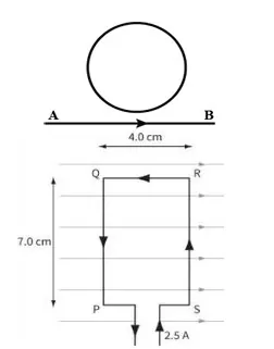
Figure: Circular loop near a straight conductor, and a rectangular frame ABCD in a magnetic field
a) State Lenz's law.
The direction of an induced current in a closed conductor is always such that it opposes the change in magnetic flux that produces it:
The negative sign expresses this opposition.
b) Show the direction of the current induced in the circular loop when the current flowing through the straight conductor AB is increasing. Write your logic.
Take the current in the straight conductor flowing upward with the loop on its right. By the right-hand thumb rule the field of the conductor passes into the page at the loop.
As the current increases, the inward flux through the loop increases. By Lenz's law the induced current must set up a field directed out of the page inside the loop to oppose this increase. By the right-hand grip rule an outward field inside the loop needs an anticlockwise induced current.
c) The figure shows a rectangular metal frame ABCD placed in a uniform magnetic field of \(4.5\times10^{-3}\ \mathrm{T}\). Obtain an expression for the e.m.f. induced in the frame.
Let the side of length \(l\) move with velocity \(v\) perpendicular to the uniform field \(B\). In a time \(dt\) the frame moves \(dx=v\,dt\), so the area enclosed by the field changes by \(dA=l\,dx=lv\,dt\) and the flux changes by
By Faraday's law
d) Calculate the force experienced by the side carrying the induced current \(I\).
The force on a conductor of length \(l\) carrying a current \(I\) in a field \(B\) is \(F=BIl\sin\theta\). For a side perpendicular to the field (\(\theta=90^\circ\)):
e) Why does the side QR not experience a force?
The force is \(F=BIl\sin\theta\), where \(\theta\) is the angle between the current direction and the field. For side QR the current is parallel (or antiparallel) to the field, so \(\theta=0^\circ\) or \(180^\circ\), \(\sin\theta=0\), and the force is zero.
a) State how Lenz's law is in accordance with the conservation of energy.
When a magnetic pole is moved towards a closed loop, the induced current gives the loop a pole of the same kind facing the magnet, so the magnet is repelled. Work must be done to push the magnet closer, and this mechanical work is converted into electrical energy and then into heat in the circuit.
If the induced effect were instead an attraction, a small push would make the magnet accelerate by itself and create energy from nothing, which violates the conservation of energy.
b) Show the direction of the current induced in the circular loop when the current flowing through the straight conductor PQ is increasing. Write your logic.
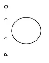
Figure: Circular loop near the straight conductor PQ
When the current in PQ increases, the flux through the nearby loop increases. If the wire is on the left of the loop and the current flows upward, the field in the loop points into the page. To oppose this increasing inward flux the loop must produce an outward field, which needs an anticlockwise induced current.
c) Name electrical inertia and find its expression for a solenoid.
Self-inductance \(L\) is called electrical inertia, because it opposes any growth or decay of current in a circuit, just as mass opposes any change of velocity.
For a long solenoid of length \(l\), area \(A\) and \(N\) turns, the field inside is \(B=\mu_0\dfrac Nl I\). The flux through one turn is \(BA\), so the total flux linkage is
Since the flux linkage is also \(LI\):
d) What is the value of the electrical inertia of a straight conductor?
A straight conductor encloses practically no area, so almost no flux links with it. Its self-inductance is therefore negligible, practically zero.
e) When a wheel with metal spokes 1.2 m long is rotated in a magnetic field of flux density \(5\times10^{-5}\ \mathrm{T}\) normal to the plane of the wheel, an e.m.f. of \(10^{-2}\ \mathrm{V}\) is induced between the rim and the axle. Find the rate of rotation of the wheel.
The e.m.f. between the axle and the rim of a rotating spoke is \(\varepsilon=\tfrac12B\omega r^2\). With \(\omega=2\pi f\):

Figure: Soft-iron core with solenoid S, coil C and Hall probe
a) State Faraday's quantitative law of electromagnetic induction.
The magnitude of the e.m.f. induced in a circuit is directly proportional to the rate of change of magnetic flux linked with it: \(\varepsilon=-N\dfrac{d\Phi}{dt}\).
b) State and explain Lenz's law.
The direction of the induced current is such that its magnetic field opposes the change in flux that produces it. If the flux through a loop is increasing, the induced current creates a field opposing the existing flux; if the flux is decreasing, it creates a field in the same direction as the existing flux, trying to maintain it. This follows from conservation of energy.
c) (i) Calculate the reading on the voltmeter connected to coil C during the time that the current is changing.
The flux density changes from \(+0.19\ \mathrm{T}\) to \(-0.19\ \mathrm{T}\), so \(|\Delta B|=0.38\ \mathrm{T}\):
(ii) Complete the table of voltmeter readings before, during and after the current is reversed.
| Condition | Before current changes | During current change | After current changes |
|---|---|---|---|
| Voltmeter on coil C (V) | 0.00 | 0.053 | 0.00 |
| Voltmeter on Hall probe (V) | 0.20 | 0.00 (while the field passes through zero) | \(-0.20\) (reversed field) |

Figure: Small coil inside a solenoid
a) (i) State Faraday's qualitative law of electromagnetic induction. (ii) Show the direction of the magnetic field inside the solenoid (arrow P).
(i) An e.m.f. is induced in a circuit whenever the magnetic flux linked with it changes.
(ii) Inside a current-carrying solenoid the field lines run along the axis from the south-pole end towards the north-pole end. Arrow P points along the axis toward the north-pole end.
b) (i) On which principle is Lenz's law based? (ii) Use Lenz's law to state and explain the direction of the field due to the induced current in the small coil.
(i) Lenz's law is based on the law of conservation of energy.
(ii) When the current is switched on, the flux through the small coil increases from zero. By Lenz's law the induced current produces a field that opposes this increase, so the field of the induced current points in the direction opposite to arrow P.
c) The small coil has an area of \(7.0\times10^{-4}\ \mathrm{m^2}\) and 75 turns. The flux density is 1.4 mT. The direction of the current is reversed in 0.12 s. Calculate the average e.m.f. induced in the small coil.
The field changes from \(+1.4\ \mathrm{mT}\) to \(-1.4\ \mathrm{mT}\), so \(\Delta B=2.8\times10^{-3}\ \mathrm{T}\):
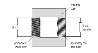
Figure: Transformer with a load resistor
a) Explain why, when there is an alternating current in the primary coil, there is a current in the load resistor connected to the secondary coil.
The alternating current in the primary produces a continuously changing magnetic flux in the soft-iron core. The core links this changing flux with the secondary coil, so by Faraday's law an alternating e.m.f. is induced across the secondary. When a load resistor is connected across the secondary, this e.m.f. drives an alternating current through it.
b) A step-down transformer is used on a 220 V line to provide a current of 0.5 A to a 15 W bulb. If the secondary has 20 turns, find the number of turns in the primary coil and the current in the primary coil.
For an ideal transformer \(P_p=P_s\):
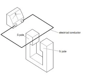
Figure: Conductor between the poles of a magnet connected to a meter
a) State a material from which an electrical conductor can be made.
Copper (or aluminium, or silver).
b) (i) State the unit of e.m.f. (ii) State what is shown by the meter when the conductor is moved horizontally from side to side and when it is moved vertically up and down.
(i) The unit of e.m.f. is the volt (V), that is, joule per coulomb.
(ii) Moved horizontally, parallel to the field lines: the meter shows zero, because no field lines are cut. Moved vertically, across the field lines: the pointer deflects, in opposite directions for upward and downward movement, because the conductor cuts the flux and an e.m.f. is induced.
c) State two factors that affect the size of the e.m.f. across the conductor.
Strength of the magnetic field: a stronger magnet gives a larger e.m.f. Speed of movement: moving the conductor faster cuts the flux at a greater rate and gives a larger e.m.f. (The length of the conductor in the field also matters.)
a) Describe and explain the readings on the centre-zero millivoltmeter as the magnet enters and leaves the coil.
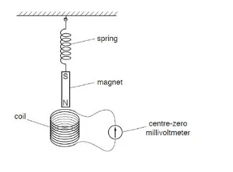
Figure: Magnet on a spring oscillating through a coil
Magnet entering the coil (moving down): the flux through the coil changes, so an e.m.f. is induced and the needle deflects to one side.
At the lowest point: the magnet is momentarily at rest, the rate of change of flux is zero and the needle returns to zero.
Magnet leaving the coil (moving up): the flux change is reversed, so the needle deflects to the opposite side.
The needle keeps swinging back and forth with a decreasing amplitude as the oscillation of the magnet dies down.
b) The figure shows the system for transmitting electricity from a power station. State the name of the device used at X and at Y.
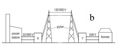
Figure: Transmission of electricity from a power station
Device X (at the power station): a step-up transformer, which raises the voltage so that the current, and hence the power loss, in the cables is small. Device Y (at the consumer end): a step-down transformer, which lowers the voltage to a safe value for use.
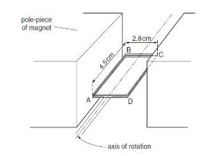
Figure: Rectangular coil between the poles of a magnet
a) For the coil in the position of maximum torque, state whether the plane of the coil is parallel to, or normal to, the direction of the magnetic field.
The torque is \(\tau=NIAB\sin\theta\), where \(\theta\) is the angle between the field and the normal to the coil. It is maximum when \(\theta=90^\circ\), that is, when the plane of the coil is parallel to the field.
b) Calculate the magnitude of the force on (i) side AB and (ii) side BC.
(i) Side AB (140 turns, \(l=0.045\ \mathrm{m}\), \(I=0.17\ \mathrm{A}\), \(B=0.070\ \mathrm{T}\)):
(ii) Side BC: this side is parallel to the field, so \(\theta=0^\circ\) and \(F_{BC}=NBIl\sin0^\circ=0\): there is no force.
c) Use your answer to (b)(i) to show that the magnetic flux density \(B\) between the poles of the magnet is 70 mT.
The two forces on AB and CD form a couple, so \(\tau_{\max}=F_{AB}\times BC\):
d) (i) State Faraday's law of electromagnetic induction. (ii) The coil is turned through \(90^\circ\) in 0.14 s, from the position where its plane is perpendicular to the field to where it is parallel. Calculate the average e.m.f. induced in the coil.
(i) The magnitude of the induced e.m.f. is directly proportional to the rate of change of flux linkage.
(ii) Initial flux linkage (plane perpendicular to the field):
Final flux linkage (plane parallel to the field) is zero, so
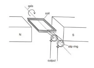
Figure: A simple AC generator
a) Explain why an e.m.f. is induced.
As the coil rotates in the field, the angle between the field lines and the normal to the coil changes continuously, so the flux linked with the coil changes continuously. By Faraday's law this induces an e.m.f. across the ends of the coil.
b) State the purpose of the slip rings.
The slip rings, with the brushes, keep a continuous electrical connection between the rotating coil and the fixed external circuit without twisting the connecting wires, so the output is an alternating current.
c) State and explain Lenz's law.
The induced current flows in the direction that opposes the change in flux producing it. In the generator the induced current in the rotating coil experiences a magnetic force that opposes the rotation, so mechanical energy must be supplied continuously to keep the coil turning. This energy is converted into electrical energy.
d) State two other ways in which the induced e.m.f. can be increased.
Increase the number of turns \(N\) of the coil, increase the strength of the magnetic field \(B\), increase the area \(A\) of the coil, or increase the speed of rotation, since \(\varepsilon_{\max}=NAB\omega\).
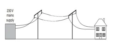
Figure: House supplied through long cables
a) Explain why the lamps are dim.
The long cables have a significant resistance \(R\). A current \(I\) in them causes a voltage drop \(IR\) and a power loss \(I^2R\) along the line. The voltage that reaches the house is therefore well below 230 V, so the lamps are dim.
b) The farmer adds transformers A and B. The lamps now light at full brightness. Explain why.
Transformer A steps the voltage up for transmission, which greatly reduces the current in the long cables. Since the power loss is \(I^2R\), the loss and the voltage drop become very small. Transformer B at the house steps the voltage back down to 230 V, so the lamps receive the full voltage and work at normal brightness.
c) Transformer A is supplied with 690 W at 230 V. (i) Calculate the current supplied to transformer A. (ii) Calculate the energy supplied to the transformer in 10 minutes.
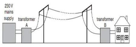
Figure: Transformers A and B between the supply and the house
(i) Current:
(ii) Energy in 10 minutes (\(t=600\ \mathrm{s}\)):
5. View PDF Notes
i. Handwritten Notes
ii. Typed PDF Notes
6. Frequently Asked Questions
What is electromagnetic induction in physics?
What are Faraday's laws of electromagnetic induction?
What is Lenz's law?
What is motional e.m.f.?
What are induced electric fields?
How does an AC generator work?
What are eddy currents and where are they used?
What are self-inductance and mutual inductance?
What is the energy stored in an inductor?
What is the working principle of a transformer?
What is the construction of a transformer?
What are the types of transformer?
What are the applications of transformers?
What are the losses and efficiency of a transformer?
Is the Transformer movie related to the electrical transformer?
What topics are included in Chapter 18 Electromagnetic Induction of NEB Class 12 Physics?
Where can I get Class 12 Physics Electromagnetic Induction notes in PDF?
Students also search for: