
Alternating Currents
Class 12 Physics Notes • NEB Syllabus 2083
Syllabus, 10 solved multiple choice questions, step-by-step numericals and derivations, handwritten and typed PDF notes and frequently asked questions on rms values, reactance, impedance, series LCR circuits, resonance and power factor.
1. Syllabus
Unit: Electricity and Magnetism
Chapter 19: Alternating Currents (8 hours)
These notes follow the NEB Class 12 Physics syllabus (+2 Physics, Nepal). Practise the multiple choice questions first, then work through the numericals, and finish with the PDF notes for quick revision.
2. Multiple Choice Questions
Question 1. When \(100\ \mathrm{V}\) DC is applied across a coil, a current of \(1\ \mathrm{A}\) flows through it. When \(100\ \mathrm{V}\) AC of \(50\ \mathrm{Hz}\) is applied to the same coil, only \(0.5\ \mathrm{A}\) flows. The inductance of the coil is:
- a) \(0.55\ \mathrm{mH}\)
- b) \(5.5\ \mathrm{mH}\)
- c) \(0.55\ \mathrm{H}\)
- d) \(55\ \mathrm{mH}\)
Correct Answer: c) \(0.55\ \mathrm{H}\)
Reason: For DC the frequency is zero, so \(X_L=0\) and the opposition is only the resistance:
For AC the impedance is \(Z=\dfrac{V}{I}=\dfrac{100}{0.5}=200\ \Omega\). Since \(Z=\sqrt{R^2+X_L^2}\):
Question 2. In an AC circuit containing \(L\), \(C\) and \(R\) in series, the resistance is \(2\ \Omega\), the capacitive reactance is \(42\ \Omega\) and the inductive reactance is \(42\ \Omega\). They are connected to a \(12\ \mathrm{V}\) supply. The current in the circuit is:
- a) \(2\ \mathrm{A}\)
- b) \(6\ \mathrm{A}\)
- c) \(12\ \mathrm{A}\)
- d) \(1.2\ \mathrm{A}\)
Correct Answer: b) \(6\ \mathrm{A}\)
Reason: Because \(X_L=X_C\), the circuit is at resonance and the impedance is minimum, \(Z=R\):
Question 3. In an inductor, the reactance \(X_L\) and the resistance \(R\) are related as:
- a) \(X_L=R\)
- b) \(X_L\gg R\)
- c) \(X_L\ll R\)
- d) \(X_L=\infty\)
Correct Answer: b) \(X_L\gg R\)
Reason: A good inductor (such as a choke) has very small ohmic resistance, and its inductive reactance \(X_L=2\pi fL\) at the working frequency is much greater than its resistance. This lets it oppose the alternating current without wasting much energy as heat.
Question 4. The resonant frequency of a circuit is \(f\). If the capacitance is made \(4\) times the initial value, the resonant frequency becomes:
- a) \(f/2\)
- b) \(2f\)
- c) \(f\)
- d) \(f/4\)
Correct Answer: a) \(f/2\)
Reason: The resonant frequency is \(f=\dfrac{1}{2\pi\sqrt{LC}}\), so \(f\propto\dfrac{1}{\sqrt C}\). With \(C\to4C\):
Question 5. The ratio of the mean value over a half cycle to the rms value of alternating current is:
- a) \(2:\pi\)
- b) \(2\sqrt2:\pi\)
- c) \(\sqrt2:\pi\)
- d) \(\sqrt2:1\)
Correct Answer: b) \(2\sqrt2:\pi\)
Reason: For a sinusoidal current of peak value \(I_0\), the mean value over a half cycle is \(\dfrac{2I_0}{\pi}\) and the rms value is \(\dfrac{I_0}{\sqrt2}\):
Question 6. In an LCR circuit, the potential difference between the terminals of the inductance is \(60\ \mathrm{V}\), between the terminals of the capacitor is \(30\ \mathrm{V}\) and between the terminals of the resistance is \(40\ \mathrm{V}\). The supply voltage is equal to:
- a) \(50\ \mathrm{V}\)
- b) \(70\ \mathrm{V}\)
- c) \(130\ \mathrm{V}\)
- d) \(10\ \mathrm{V}\)
Correct Answer: a) \(50\ \mathrm{V}\)
Reason: The voltages are out of phase, so they are added as phasors, not as simple numbers:
Question 7. A capacitor of capacitance \(1\ \mu\mathrm{F}\) is charged to a potential of \(1\ \mathrm{V}\). It is connected in parallel to an inductor of inductance \(10^{-3}\ \mathrm{H}\). The maximum current that will flow in the circuit has the value:
- a) \(\sqrt{1000}\ \mathrm{mA}\)
- b) \(1\ \mathrm{mA}\)
- c) \(1\ \mu\mathrm{A}\)
- d) \(1000\ \mathrm{mA}\)
Correct Answer: a) \(\sqrt{1000}\ \mathrm{mA}\)
Reason: By conservation of energy in the LC oscillation, the maximum energy stored in the capacitor equals the maximum energy stored in the inductor:
Question 8. A step-down transformer is connected to a \(2400\ \mathrm{V}\) line and \(80\ \mathrm{A}\) of current is found to flow in the output load. The ratio of the turns in the primary and secondary coils is \(20:1\). If the efficiency of the transformer is \(100\%\), the current flowing in the primary coil is:
- a) \(1600\ \mathrm{A}\)
- b) \(20\ \mathrm{A}\)
- c) \(4\ \mathrm{A}\)
- d) \(1.5\ \mathrm{A}\)
Correct Answer: c) \(4\ \mathrm{A}\)
Reason: For an ideal transformer the power in the primary equals the power in the secondary, \(V_pI_p=V_sI_s\), so the currents are in the inverse ratio of the turns:
Question 9. The reactance of a capacitor of \(C\ \mu\mathrm{F}\) for alternating current of frequency \(\dfrac{400}{\pi}\ \mathrm{Hz}\) is \(25\ \Omega\). The value of \(C\) is:
- a) 100
- b) 50
- c) 450
- d) 25
Correct Answer: b) 50
Reason: Using \(X_C=\dfrac{1}{2\pi fC}\):
Question 10. What is the phase difference between the virtual (rms) voltage and the virtual (rms) current when the current in the circuit is wattless?
- a) \(65^\circ\)
- b) \(180^\circ\)
- c) \(90^\circ\)
- d) \(45^\circ\)
Correct Answer: c) \(90^\circ\)
Reason: The average power is \(P=V_{rms}I_{rms}\cos\phi\). A wattless current consumes no power, so \(\cos\phi=0\), which means \(\phi=90^\circ\). This happens in a circuit containing only an ideal inductor or an ideal capacitor.
3. Numerical and Subjective Questions
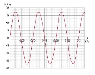
Figure for Question 1
a) What is the peak value of the current?
The peak value \(I_0\) is the maximum displacement of the waveform from the time axis. Read the value of \(I\) at the crest of the wave on the vertical axis.
b) State the value of the alternating current when the time is \(0.23\ \mathrm{s}\).
Read \(I_0\) and the frequency \(f\) from the graph and use the equation of the current, taking the origin at a zero crossing:
Substitute \(t=0.23\ \mathrm{s}\), together with \(I_0\) and \(f\) from the graph, to get the instantaneous current. The same value can also be read directly from the graph at \(t=0.23\ \mathrm{s}\).
c) Find the time period and the frequency of the alternating current shown in the figure.
The time period \(T\) is the time taken for one complete cycle (one positive and one negative half cycle), read along the time axis. The frequency is its reciprocal:
For example, if one cycle occupies \(0.04\ \mathrm{s}\), then \(f=\dfrac{1}{0.04}=25\ \mathrm{Hz}\).
d) Find the rms and the mean value of the alternating current.
For a sinusoidal current of peak value \(I_0\):
The mean value over a complete cycle is zero, because the positive and negative half cycles cancel.
a) What is the power factor of a pure capacitive circuit?
In a pure capacitive circuit the current leads the voltage by \(90^\circ\), so the phase angle is \(\phi=90^\circ\):
b) Obtain an expression for the phase relationship between the current and the voltage in a pure capacitive circuit.
Let the applied voltage be \(V=V_0\sin\omega t\). The charge on the capacitor is \(q=CV=CV_0\sin\omega t\). The current is the rate of flow of charge:
Writing \(\cos\omega t=\sin\left(\omega t+\dfrac\pi2\right)\) and \(I_0=CV_0\omega=\dfrac{V_0}{1/\omega C}\):
The current leads the voltage by \(\dfrac\pi2\) (\(90^\circ\)). The quantity \(X_C=\dfrac1{\omega C}\) is the capacitive reactance.
Figure: Voltage and current in a pure capacitive circuit
c) Why is a pure capacitive circuit an open circuit for direct current?
The capacitive reactance is \(X_C=\dfrac{1}{2\pi fC}\). For direct current \(f=0\), so \(X_C\to\infty\). The capacitor offers infinite opposition and does not allow a steady current to pass, so it behaves as an open circuit.
d) An iron-cored coil of inductance \(2\ \mathrm{H}\) and resistance \(50\ \Omega\) is placed in series with a resistor of \(450\ \Omega\), and a \(200\ \mathrm{V}\), \(50\ \mathrm{Hz}\) alternating supply is connected across the arrangement. Find the current flowing in the coil, its phase angle relative to the supply voltage and the voltage across the coil.
Total resistance and inductive reactance:
Impedance and current (the same current flows through the coil, since it is a series circuit):
Phase angle:
Voltage across the coil, whose own impedance is \(Z_c=\sqrt{r^2+X_L^2}\):
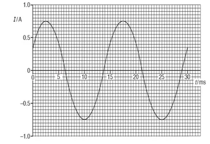
Figure for Question 3
a) Define the rms value of alternating current.
The root mean square (rms) value of an alternating current is that value of steady direct current which produces the same amount of heat in a given resistance in a given time as the alternating current does when it flows through the same resistance for the same time.
b) i) The variation with time \(t\) of the sinusoidal current \(I\) in a resistor of resistance \(450\ \Omega\) is shown in the figure. Use the data from the figure to determine, for the time \(t=0\) to \(t=30\ \mathrm{ms}\), the frequency of the current.
The figure shows one and a half cycles in \(30\ \mathrm{ms}\), so the time period is \(T=20\ \mathrm{ms}=0.02\ \mathrm{s}\):
b) ii) The mean current.
Over a whole number of cycles the mean current is zero. From \(0\) to \(30\ \mathrm{ms}\) the net area under the graph is that of one half cycle, whose area is \(I_0\cdot\dfrac T\pi\). With \(I_0=0.75\ \mathrm{A}\):
(If the question means the mean over a half cycle, the value is \(\dfrac{2I_0}{\pi}=\dfrac{2\times0.75}{\pi}\approx0.48\ \mathrm{A}\).)
b) iii) The root-mean-square (rms) current.
The peak current read from the figure is \(I_0\approx0.75\ \mathrm{A}\):
b) iv) The energy dissipated by the resistor.
The energy dissipated is the heat produced by the rms current:
a) What is the power factor of a pure inductive circuit?
In a pure inductive circuit the current lags the voltage by \(90^\circ\), so \(\cos\phi=\cos90^\circ=0\). The power factor is zero.
b) Obtain an expression for the phase relationship between the current and the voltage in a pure inductive circuit.
Let the current be \(I=I_0\sin\omega t\). The voltage applied must overcome the induced e.m.f., so \(V=L\dfrac{dI}{dt}\):
where \(V_0=\omega LI_0\). The voltage leads the current by \(\dfrac\pi2\), that is, the current lags the voltage by \(90^\circ\). The quantity \(X_L=\omega L\) is the inductive reactance.
Figure: Voltage and current in a pure inductive circuit
c) Why is a pure inductive circuit a short circuit for direct current?
The inductive reactance is \(X_L=2\pi fL\). For direct current \(f=0\), so \(X_L=0\). An ideal inductor with no ohmic resistance then offers no opposition to a steady current and behaves as a short circuit.
d) A coil having inductance and resistance is connected to an oscillator giving a fixed sinusoidal output voltage of \(5\ \mathrm{V}\) rms. At a frequency of \(50\ \mathrm{Hz}\) the rms current in the coil is \(1\ \mathrm{A}\), and at \(100\ \mathrm{Hz}\) the rms current is \(0.625\ \mathrm{A}\). Determine the inductance of the coil.
The impedances are \(Z_1=\dfrac{5}{1}=5\ \Omega\) and \(Z_2=\dfrac{5}{0.625}=8\ \Omega\). With \(Z^2=R^2+(2\pi fL)^2\):
Subtracting (1) from (2):
The inductance of the coil is \(L\approx11.5\ \mathrm{mH}\).
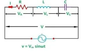
Figure for Question 5
a) Write the relationship between the current and the voltage.
For an applied voltage \(V=V_0\sin\omega t\) the current is
where the impedance is \(Z=\sqrt{R^2+(X_L-X_C)^2}\).
b) Draw the phasor diagram to show the lagging or leading relationship of the voltage and the current in the circuit.
Draw the current phasor \(I\) along the reference axis. \(V_R\) is drawn along \(I\), \(V_L\) is drawn \(90^\circ\) ahead of \(I\), and \(V_C\) is drawn \(90^\circ\) behind \(I\). The net reactive voltage is \(V_L-V_C\), and the supply voltage \(V\) is the vector sum of \(V_R\) and \((V_L-V_C)\), making an angle \(\phi\) with \(I\). The figure shows the case \(X_L>X_C\), in which the voltage leads the current.
Figure: Phasor diagram of a series LCR circuit
c) In a series LCR circuit, \(R=25\ \Omega\), \(L=30\ \mathrm{mH}\) and \(C=10\ \mu\mathrm{F}\). The elements are connected to a \(240\ \mathrm{V}\), \(50\ \mathrm{Hz}\) alternating source. Calculate the current in the circuit and the voltmeter reading across the capacitor.
a) Write the expression for the impedance of an LCR circuit.
The impedance of a series LCR circuit is
b) Find the condition of resonance in an LCR circuit.
Resonance occurs when the reactive part of the impedance is zero, that is, when the inductive reactance equals the capacitive reactance:
Then \(Z=R\) is minimum and the current is maximum.
Figure: Resonance curve of a series LCR circuit
c) A circuit consists of a capacitor of \(2\ \mu\mathrm{F}\) and a resistor of \(1000\ \Omega\). An alternating e.m.f. of \(12\ \mathrm{V}\) (rms) and frequency \(50\ \mathrm{Hz}\) is applied. Find the current flowing, the voltage across the capacitor and the phase angle between the applied e.m.f. and the current.
The current leads the applied e.m.f. by \(57.9^\circ\).
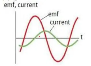
Figure for Question 7
i) Explain whether the phase constant is positive or negative.
Take the e.m.f. as \(V=V_0\sin\omega t\) and the current as \(I=I_0\sin(\omega t-\phi)\). When the current peak comes after the e.m.f. peak (the current lags), the phase constant \(\phi\) is positive. If the current peak comes before the e.m.f. peak (the current leads), \(\phi\) is negative. For the case in which the current lags the voltage, as is usual when \(X_L>X_C\), \(\phi\) is positive.
ii) Sketch a phasor diagram for the given case.
For the case where the current lags, draw the current phasor \(I\) horizontally. The voltage phasor \(V\) is drawn at an angle \(\phi\) ahead of \(I\) (anticlockwise), with \(V_L\) longer than \(V_C\), as shown.
Figure: Phasor diagram when the current lags the voltage
iii) Is the circuit more inductive or capacitive? Explain.
If the voltage leads the current (the current lags), the circuit is more inductive, because \(X_L>X_C\) and \(\tan\phi=\dfrac{X_L-X_C}{R}\) is positive. (If the graph shows the current leading the voltage, the circuit is more capacitive, with \(X_C>X_L\).)
iv) To increase the rate at which energy is transferred to the resistive load, should the inductance be increased or decreased? Justify your answer.
The rate of energy transfer to the resistor is \(P=I_{rms}^2R\), so the current must be increased. The current is \(I=\dfrac VZ\), so the impedance \(Z=\sqrt{R^2+(X_L-X_C)^2}\) must be made smaller. For an inductive circuit (\(X_L>X_C\)) this means decreasing the inductance, which brings \(X_L\) closer to \(X_C\), towards resonance, where \(Z=R\) is minimum and the power transferred to the load is maximum.
a) Discuss the phase relationship between the voltage and the current in an alternating current circuit containing a capacitor and a resistor in series, and hence derive the expression for the impedance of the circuit.
Let the current be \(I=I_0\sin\omega t\). The voltage across the resistor, \(V_R=IR\), is in phase with the current. The voltage across the capacitor, \(V_C=IX_C\), lags the current by \(90^\circ\). From the phasor diagram, \(V_R\) and \(V_C\) are perpendicular, and the applied voltage is their resultant:
The ratio \(V/I\) is the impedance \(Z\):
The current leads the applied voltage by an angle \(\phi\) given by \(\tan\phi=\dfrac{V_C}{V_R}=\dfrac{X_C}{R}\).
Figure: Phasor diagram of a resistor and a capacitor in series
b) An air-core coil and an electric bulb are connected in series across a \(220\ \mathrm{V}\), \(50\ \mathrm{Hz}\) alternating source. The bulb glows with some brightness. How will the glow of the bulb be affected on introducing a capacitor in series in the circuit?
Before the capacitor is added, the impedance is \(Z_1=\sqrt{R^2+X_L^2}\). After it is added, the impedance is \(Z_2=\sqrt{R^2+(X_L-X_C)^2}\). The capacitive and inductive reactances act in opposite senses, so \(Z_2
a) Define the impedance of an LCR circuit.
The total effective opposition offered by a series combination of a resistor, an inductor and a capacitor to the flow of alternating current is called the impedance \(Z\) of the circuit. Its unit is the ohm.
b) i) A series LCR circuit is connected across an alternating source of e.m.f. \(50\ \mathrm{V}\) and frequency \(50\ \mathrm{Hz}\), with \(L=60\ \mathrm{mH}\), \(C=0.50\ \mu\mathrm{F}\) and \(R=300\ \Omega\). Calculate the impedance of the circuit.
b) ii) How does resonance occur in the above circuit? Write the required expression.
Resonance occurs when the inductive and capacitive reactances become equal, \(X_L=X_C\), so that the impedance falls to its minimum value \(Z=R\). This happens when the frequency of the source is adjusted to
For the given values, \(f_0=\dfrac{1}{2\pi\sqrt{0.06\times0.5\times10^{-6}}}\approx919\ \mathrm{Hz}\).
c) i) A device X is connected across an alternating source of voltage \(V=V_0\sin\omega t\), and the current through X is \(I=I_0\sin(\omega t+\pi/2)\). Identify the device X and write an expression for its reactance.
The current leads the voltage by \(\dfrac\pi2\), so the device X is a pure capacitor. Its reactance is
c) ii) Draw a graph showing the variation of voltage and current over one cycle of the alternating current for X.
The voltage is a sine curve starting from zero. The current is a cosine curve: it starts at its positive maximum, so it is always a quarter of a cycle ahead of the voltage.
Figure: Voltage and current for a capacitor
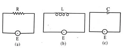
Figure for Question 10
a) What is wattless current?
In a circuit containing only an ideal inductor or an ideal capacitor the phase difference between the voltage and the current is \(90^\circ\), so the average power is \(P=VI\cos90^\circ=0\). The current that flows without consuming any power is called wattless current.
b) i) If the frequency of the e.m.f. is increased, what will be the effect on the current flowing in them? Explain.
b) ii) What difference do you expect in the opposition provided by the circuit for the current flow in figures (a) and (b) if the given alternating e.m.f. is replaced by an equivalent direct e.m.f.?
a) Define resonance in an alternating current circuit with one example.
Resonance is the condition in a series LCR circuit in which the inductive reactance equals the capacitive reactance, \(X_L=X_C\). The impedance is then purely resistive and minimum, so the current is maximum. Example: the tuning circuit of a radio receiver, in which the capacitance is varied until the resonant frequency of the circuit matches the frequency of the station.
b) Prove that the resonant frequency of an alternating current circuit is \(f=\dfrac{1}{2\pi\sqrt{LC}}\).
At resonance the reactances are equal:
Putting \(\omega=2\pi f\):
c) The maximum capacitance of a variable capacitor is \(33\ \mathrm{pF}\). What should be the self-inductance to be connected to this capacitor so that the natural frequency of the LC circuit is \(810\ \mathrm{kHz}\), corresponding to the AM broadcast band of Radio Nepal?
4. View PDF Notes
i. Handwritten Notes
ii. Typed PDF Notes
5. Frequently Asked Questions
What is alternating current in physics?
What topics are included in Chapter 19 Alternating Currents of NEB Class 12 Physics?
What is the difference between AC and DC current?
What are examples of AC and DC current?
What is alternating current used for?
What are the peak value, rms value and mean value of alternating current?
What is the rms value of alternating current?
What is the phase relation between current and voltage in a resistor, a capacitor and an inductor?
Why is a capacitor an open circuit for DC and an inductor a short circuit for DC?
What is a phasor diagram?
What are the formulas for impedance and phase angle of a series LCR circuit?
What is resonance in a series LCR circuit and what is the quality factor?
What is power factor and what is wattless current?
What is the formula for the resonant frequency of an LC circuit?
Is Alternating Currents Starfield related to this chapter?
Where can I get Class 12 Physics Chapter 19 Alternating Currents notes in PDF?
Students also search for: